Slickline Anti BlowOut Tool
Technical Description and Specifications
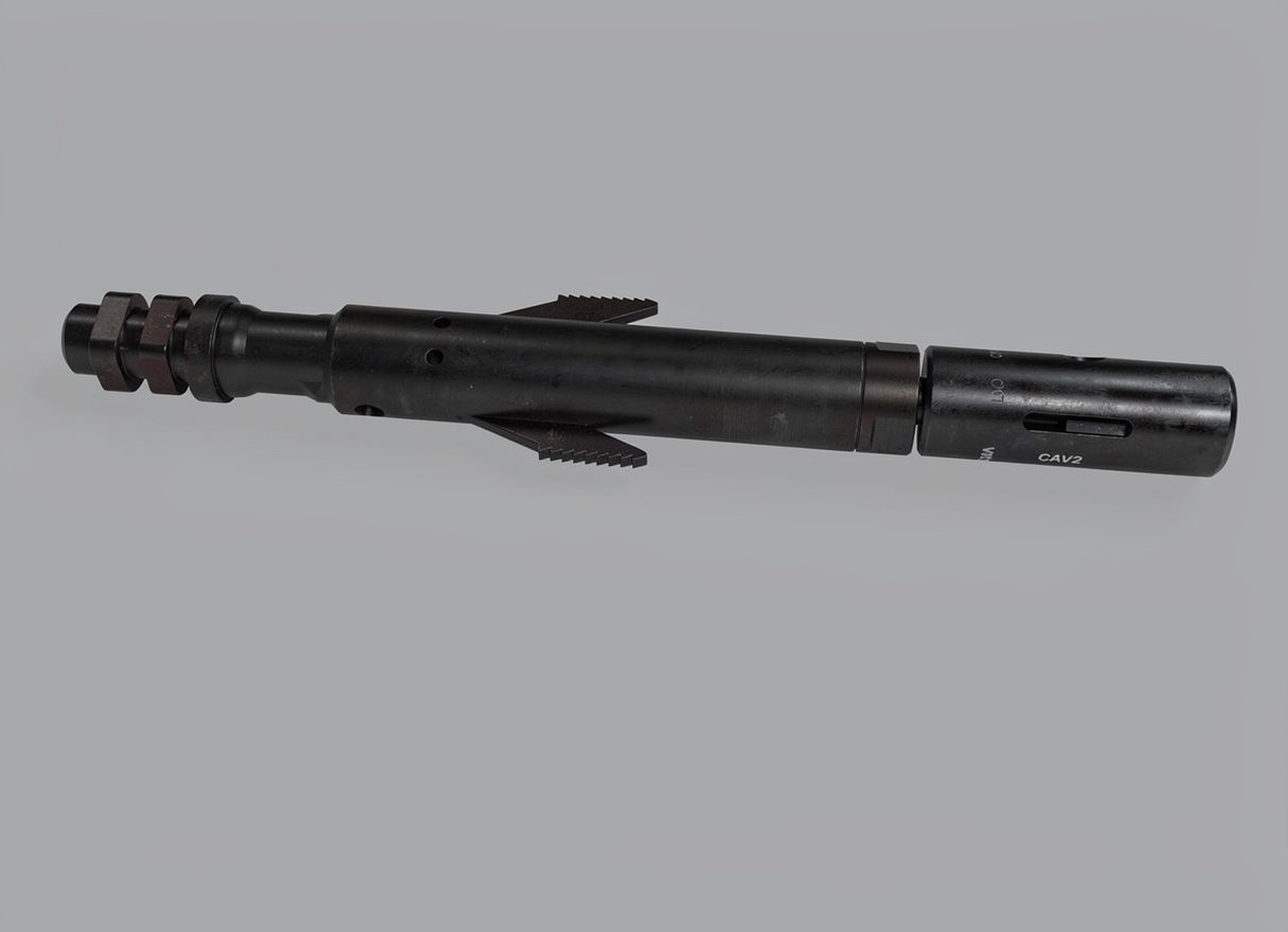
The Slickline Anti-Blow-Out Tool is a critical safety component used in high-velocity gas wells or wells with significant bottom-hole pressure. Its primary purpose is to prevent the “blow-up” effect—a dangerous scenario where high-velocity gas flow or a sudden surge in production force the tool string upward faster than the winch can retrieve the wire. This causes the wire to slacken, “bird-nest” in the lubricator, and potentially kink or break, leading to a catastrophic loss of the BHA and a potential well control incident.
Key Technical Specifications and Operation
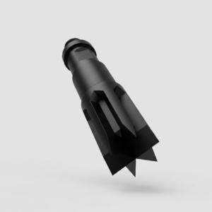
Centrifugal Brake/Latching Mechanism: The tool contains a series of internal “dogs” or friction elements. During normal operations (ascent or descent), the tool remains inactive. However, if the tool string exceeds a pre-set upward velocity (the “blow-up” speed), the internal mechanism expands and locks against the tubing wall.
Controlled Descent: Once the tool has latched to prevent the blow-up, it is designed to be “reset” or released by applying downward tension or jarring. Some models act as a friction brake, slowing the ascent to a safe speed rather than a hard lock.
Safety in Gas Wells: This tool is essential when running lightweight BHAs or gauges in gas-lift wells or high-productivity gas injectors where the differential pressure can easily overcome the weight of the stem.
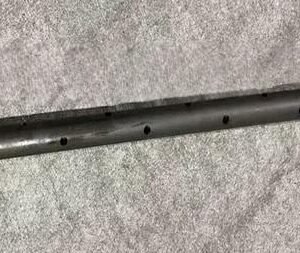
Fluid Bypass: The tool body is designed with large bypass channels to ensure that well fluids do not prematurely activate the tool during high-speed tripping operations.
Integral Fish Neck: Features a standard industry fish neck on top, allowing for standard recovery if the tool string becomes stuck or the wire is severed.
Customization and Materials
Material: Typically manufactured from 4140 Alloy Steel or 17-4 PH Stainless Steel. For sour service, all components are heat-treated to meet NACE MR0175 standards.
Sensitivity Adjustment: The activation speed can often be adjusted by changing internal springs or “shear pins” to match the specific flow characteristics and pressure profile of the well.
Connection Profile: Standard 15/16″ or 1-1/16″ UN pin/box connections to integrate seamlessly into the BHA, usually positioned just below the rope socket.
Critical Parameters
| Parameter | Customizable Range |
| Tool OD (Outside Diameter) | 1.25″, 1.50″, 1.75″, 2.125″ |
| Activation Velocity | Adjustable via spring tension |
| Bore Size Compatibility | 2.375″ to 4.50″ Tubing |
| Material Standards | AISI 4140 / 17-4 PH / NACE MR0175 |
| Max Working Pressure | Matches PCE Rating (up to 15,000 psi) |

Reviews
There are no reviews yet.